X

It is combined with the intelligent positioner (1500/1600/1880) and the angle seat valve(2710). The spool design of the 2710 series angle seat valve (control type) is different from the 2700 series angle seat valve (on-off type). Its flow characteristic is more suitable for the flow adjustment.
| Material |
Positioner material: PC, SI, PA6-GF30 Valve material: SS304(CF8) / SS316(CF8M) Actuator material: SS304(CF8) Sealling material: PTFE |
| Power supply | 24V DC ±10% |
| Input signal | 4 – 20 mA |
|
Input resistance |
120Ω |
| Temperature range |
Positioner ambient:0-70°C Valve medium:-20-180℃ Valve ambient:-10-60℃ |
| Valve connection | Thread, Clamp, Welded, Flange |
| Air supply | 3-7 Bar |
| Pneumatic connector | Plug-in hose connector G1/4(internal Φ6mm) |
| Electrical connector |
M12 3-pins B-coded(cable ø4-6mm) M12 4-pins D-coded(cable ø4-6mm) |
|
Valve size |
DN15-DN100 |
| Working pressure | 16 Bar |
|
Medium |
Water, neutral gas, water vapor, weak acid or weak base solution |
| Protetion class | IP66 |
|
Medium viscosity |
Max 600mm²/s |
| Consumption | <5W |
| Material |
Positioner material: PC, PA6-GF30, Stainless Steel, Si Valve material: SS304(CF8) / SS316(CF8M) Actuator material: SS304(CF8) Sealling material: PTFE |
| Power supply | 24V DC ±10% |
| Input signal |
0/4-20mA or 0-5/10 V |
|
Input resistance |
240Ω at 0/4-20mA, 21KΩ at 0-5/10V |
| Temperature range |
Positioner ambient: 0-70°C Valve medium: -20-180℃ Valve ambient: -10-60℃ |
| Valve connection | Thread, Clamp, Welded, Flange |
| Air supply | 3-7 Bar |
| Pneumatic connector | Plug-in hose connector G1/4(internal Φ6mm) |
| Electrical connector |
M12 3-pins B-coded(cable ø4-6mm) M12 4-pins D-coded(cable ø4-6mm) M12 5-pins A-coded(cable ø4-6mm) |
| Valve size | DN15-DN100 |
| Working pressure | 16 Bar |
| Medium | Water, neutral gas, water vapor, weak acid or weak base solution |
| Protetion class | IP66 |
| Medium viscosity | Max 600mm²/s |
|
Consumption |
<5W |
| Material |
Positioner material: PC, PA6-GF30, Si Valve material: SS304(CF8) / SS316(CF8M) Actuator material: SS304(CF8) Sealling material: PTFE
|
| Power supply | 24V DC ±10% |
| Input signal |
0/4 - 20mA |
| Input resistance | 120Ω |
| Temperature range |
Positioner ambient:0-70°C Valve medium:-20-180℃ Valve ambient:-10-60℃
|
| Valve connection |
Thread, Clamp, Welded, Flange
|
| Air supply | 3-7 Bar |
| Pneumatic connector |
Plug-in hose connector G1/4(internal Φ6mm) |
| Electrical connector |
M12 2-pins B-coded(cable ø4-6mm) M12 4-pins D-coded(cable ø4-6mm) |
| Valve size | DN15-DN40 |
|
Working pressure |
16 Bar |
|
Medium |
Water, neutral gas, water vapor, weak acid or weak base solution |
|
Protetion class |
IP66 |
| Medium viscosity | Max 600mm²/s |
| Consumption | <5W |
The positioner and valve are connected by thread. The user can tighten them with a No. 32 wrench.
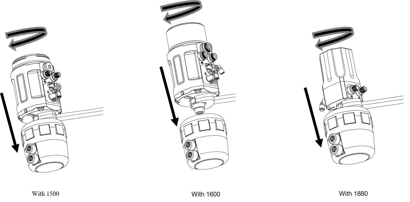
After the positioner is assembled, it can still be rotated within 720° for proper operator interface angle.


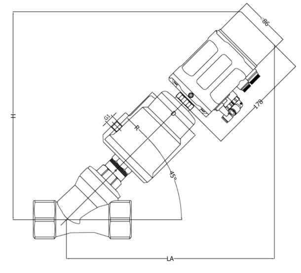
Screw thread & Welding(ASME BPE) (Unit: mm)
| Size | Actuator | D | R | G1 | H/LA(Screw) | H/LA(Weld) |
| DN15 | 63 | 77 | 41.5 | G1/8 | 279 | 280 |
| DN20 | 63 | 77 | 41.5 | G1/8 | 283 | 279 |
| DN25 | 63 | 77 | 41.5 | G1/8 | 289 | - |
| DN32 | 80 | 98 | 52 | G1/4 | 314 | - |
| DN40 | 80 | 98 | 52 | G1/4 | 322 | 314 |
| DN50 | 80 | 98 | 52 | G1/4 |
332 |
322 |
| DN65 | 100 | 98 | 63 |
G1/4 |
374 | 350 |
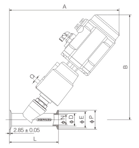
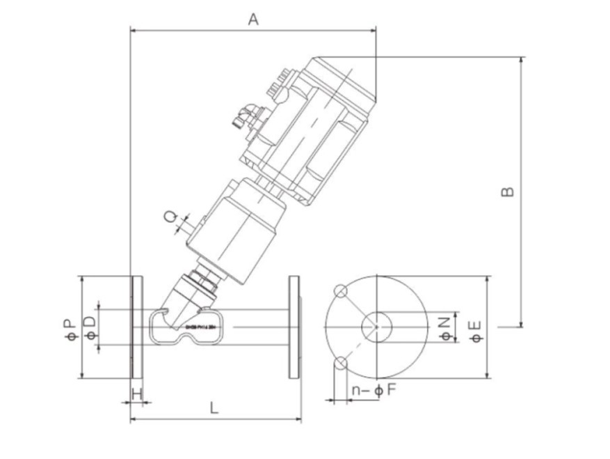
Clamp connection (Unit: mm)
| Size | Actuator | A | B | O | L | ΦD |
ΦE |
ΦN |
ΦP |
| DN20 | 63 | 276 | 270 | G1/8 | 111 | 24 | 43.5 | 20 | 50.5 |
| DN25 | 63 | 289 | 282 | G1/8 | 130 | 32 | 43.5 | 27 | 50.5 |
| DN32 | 80 | 333 | 312 | G1/8 | 140 | 38 | 43.5 | 32 | 50.5 |
| DN40 | 80 | 327 | 309 | G1/8 | 160 | 46 | 56.5 | 40 | 64 |
| DN50 | 80 | 353 | 330 | G1/8 | 175 | 57 | 70.5 | 50 | 77.5 |
| DN65 | 100 | 403 | 400 | G1/4 |
246 |
76 | 83.5 | 72 | 91 |
| DN80 | 125 | 438 | 435 |
G1/4 |
263 | 89 | 97 | 83 | 106 |
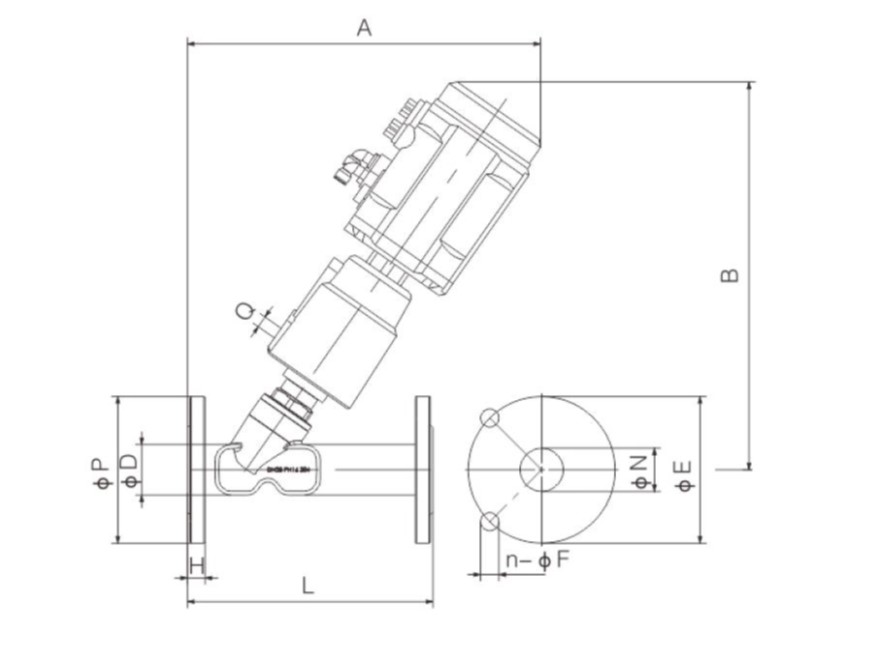
Flange connection(Unit: mm)
| Size | Actuator | A | B | O | L | ΦD |
ΦE |
ΦN |
n-ΦF |
ΦP |
H |
| DN20 | 63 | 263 | 292 | G1/8 | 176 | 31 | 75 | 26 | 4-14 | 102 | 13.5 |
| DN25 | 63 | 269 | 303 | G1/8 | 188 | 39 | 85 | 33 | 4-14 | 112 | 13.5 |
| DN32 | 80 | 318 | 337 | G1/8 | 200 | 45 | 100 | 39 | 4-18 | 132 | 14.5 |
| DN40 | 80 | 318 | 332 | G1/8 | 223 | 52 | 110 | 46 | 4-18 | 142 | 15.5 |
| DN50 | 80 | 327 | 342 | G1/8 | 230 | 66 | 125 | 59 | 4-18 | 157 | 16 |
| DN65 | 100 | 393 | 389 | G1/4 |
235 |
88 | 145 | 78 | 4-18 | 177 | 17 |
| DN80 | 125 | 393 | 427 |
G1/4 |
258 | 102 | 160 | 91 | 8-18 | 192 | 18 |
Screw thread & Welding(ASME BPE) (Unit: mm)
| Size | Actuator | D | R | G1 | H/LA(Screw) | H/LA(Weld) |
| DN15 | 63 | 77 | 41.5 | G1/8 | 298 | 299 |
| DN20 | 63 | 77 | 41.5 | G1/8 | 302 | 298 |
| DN25 | 63 | 77 | 41.5 | G1/8 | 308 | - |
| DN32 | 80 | 98 | 52 | G1/4 | 333 | - |
| DN40 | 80 | 98 | 52 | G1/4 | 341 | 333 |
| DN50 | 80 | 98 | 52 | G1/4 |
351 |
341 |
| DN65 | 100 | 98 | 63 |
G1/4 |
393 | 369 |

Clamp connection (Unit: mm)
| Size | Actuator | A | B | O | L | ΦD |
ΦE |
ΦN |
ΦP |
| DN20 | 63 | 282 | 287 | G1/8 | 111 | 24 | 43.5 | 20 | 50.5 |
| DN25 | 63 | 295 | 299 | G1/8 | 130 | 32 | 43.5 | 27 | 50.5 |
| DN32 | 80 | 339 | 329 | G1/8 | 140 | 38 | 43.5 | 32 | 50.5 |
| DN40 | 80 | 333 | 326 | G1/8 | 160 | 46 | 56.5 | 40 | 64 |
| DN50 | 80 | 359 | 347 | G1/8 | 175 | 57 | 70.5 | 50 | 77.5 |
| DN65 | 100 | 409 | 417 | G1/4 |
246 |
76 | 83.5 | 72 | 91 |
| DN80 | 125 | 442 | 452 |
G1/4 |
263 | 89 | 97 | 83 | 106 |
Flange connection(Unit: mm)
| Size | Actuator | A | B | O | L | ΦD |
ΦE |
ΦN |
n-ΦF |
ΦP |
H |
| DN20 | 63 | 269 | 309 | G1/8 | 176 | 31 | 75 | 26 | 4-14 | 102 | 13.5 |
| DN25 | 63 | 275 | 320 | G1/8 | 188 | 39 | 85 | 33 | 4-14 | 112 | 13.5 |
| DN32 | 80 | 324 | 354 | G1/8 | 200 | 45 | 100 | 39 | 4-18 | 132 | 14.5 |
| DN40 | 80 | 324 | 349 | G1/8 | 223 | 52 | 110 | 46 | 4-18 | 142 | 15.5 |
| DN50 | 80 | 333 | 359 | G1/8 | 230 | 66 | 125 | 59 | 4-18 | 157 | 16 |
| DN65 | 100 | 399 | 386 | G1/4 |
235 |
88 | 145 | 78 | 4-18 | 177 | 17 |
| DN80 | 125 | 433 | 444 |
G1/4 |
258 | 102 | 160 | 91 | 8-18 | 192 | 18 |
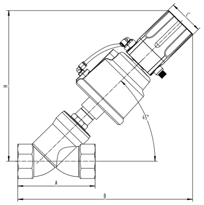
Screw thread connection(Unit: mm)
| Size | Actuator | A | B | C | H | H/LA(Weld) |
| DN15 | 63 | 65 | 255 | 69 | 238 | 280 |
| DN20 | 63 | 75 | 263 | 69 | 252 | 279 |
| DN25 | 80 | 90 | 282 | 69 | 258 | |
| DN32 | 80 | 110 | 298 | 69 | 266 | - |
| DN40 | 100 | 120 | 321 | 69 | 288 | 314 |
| DN50 | 100 | 150 | 339 | 69 |
298 |
322 |
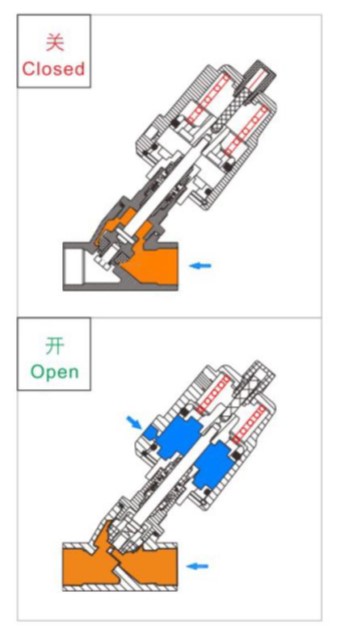
| DN | Actuator(mm) | Control pressure(Mpa) | Working pressure(Mpa) |
|
15 |
63 | 0.4-0.6 | 0-1.6 |
|
20 |
63 |
0.4-0.6 |
0-1.6 |
|
25 |
63 |
0.4-0.6 |
0-1.6 |
|
32 |
80 | 0.5-0.7 |
0-1.6 |
|
40 |
80 |
0.5-0.7 |
0-1.6 |
|
50 |
80 | 0.6-0.9 |
0-1.6 |
|
65 |
100 |
0.4-0.9 |
0-1.6 |
| 80 | 120 |
0.4-0.9 |
0-1.6 |
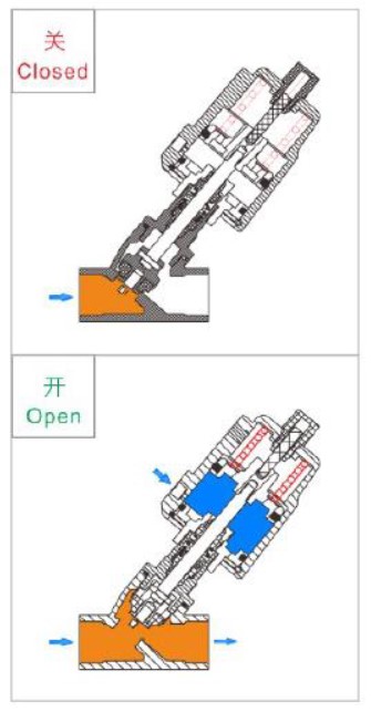
| DN | Actuator(mm) | Control pressure(Mpa) | Working pressure(Mpa) |
|
15 |
63 | ≥0.45 | 0-1.2 |
|
20 |
63 |
≥0.45 |
0-1.2 |
|
25 |
63 |
≥0.45 |
0-1.2 |
|
32 |
80 | ≥0.5 |
0-1.2 |
|
40 |
80 |
≥0.5 |
0-1.2 |
|
50 |
80 | ≥0.6 |
0-0.8 |
|
65 |
100 |
≥0.6 |
0-0.4 |
| Size | 10% | 20% | 30% | 40% | 50% | 60% | 70% | 80% | 90% | 100% |
| 2710(DN15) | 0.2 | 0.48 | 0.69 | 0.86 | 1.10 | 1.58 | 2.12 | 2.48 | 3.15 | 3.17 |
|
2710(DN20) |
1.0 | 1.7 | 2.4 | 3.1 | 3.8 | 5.1 | 6.9 | 8.5 | 9.5 | 11.6 |
| 2710(DN32) | 1.77 | 2.48 | 3.10 | 3.8 | 4.45 | 5.6 | 8.44 | 12.1 | 15.32 | 16.92 |
| 2710(DN40) | 0.88 | 1.88 | 2.71 | 3.44 | 4.57 | 7.02 | 10.61 | 14.65 | 19.1 | 19.94 |
| 2710(DN50) | 1.49 | 2.81 | 4.11 | 5.03 | 6.84 | 12.36 | 19.29 | 27.53 | 32.68 | 35.93 |